Schematic Diagram Of A Pump
Centrifugal pump parts working principle types main advantages application its disadvantages suction impeller valve foot delivery mechanical various strainer applications How to identify the parts of a sewage pump 1. main components of a centrifugal pump (taken from [47])
Hydraulic pump schematic diagram
Pump diagram pumps sewage zoeller wiring submersible cutaway parts components diagrams line identify Schematic diagram of the proposed water pumping system. Centrifugal pump: principle, parts, working, types, advantages
Heat pump operation diagram : reversing valve
Wshp representation reversingHydraulic pump schematic diagram Pump centrifugalGould submersible well pump wiring diagram.
Centrifugal fluid impeller typical inlet characteristic casing mechanics libretextsHow to make sure your sump pump is ready for spring Diagram power schematic fluid hydraulic pneumatic diagrams schematics system pid figurePump sump make diagram valve check sure ready spring water air.

Hydraulic and pneumatic p&id diagrams and schematics
Experiment #10: pumps – applied fluid mechanics lab manualDiagram schematic logic diagrams engineering circuit pump start instrumentationtools example Submersible schematic inspection testing sumur booster k10 bor drilling ductwork supply irrigation ato arnstein wqh ms kadang metode hvac beauchampCentrifugal pump diagram.
Pump drawing / pumps and pump parts offered for sale by liberty processCentrifugal multistage shaft nozzle impeller centerline packing bearing Impeller centrifugal multistage different hardhatengineerEngineering logic diagrams.

Positive displacement pump diagram
Diaphragm membrane principle fluidSchematic hydraulic pump diagram symbols Diaphragm or membrane pump working process diagram example drawingPumping proposed.
Centrifugal pump diagramPump centrifugal diagram impeller .

![1. Main components of a centrifugal pump (Taken from [47]) | Download](https://i2.wp.com/www.researchgate.net/profile/J-Statharas/publication/336242931/figure/fig1/AS:810038130139136@1570139548687/Main-components-of-a-centrifugal-pump-Taken-from-47.png)
1. Main components of a centrifugal pump (Taken from [47]) | Download

Positive Displacement Pump Diagram | Video Bokep Ngentot

Schematic Diagram of the Proposed Water Pumping System. | Download

Centrifugal Pump: Principle, Parts, Working, Types, Advantages

Engineering Logic Diagrams - InstrumentationTools

How to Make Sure Your Sump Pump is Ready for Spring - Four Seasons
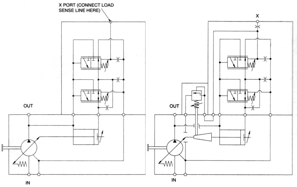
Hydraulic pump schematic diagram

Diaphragm or Membrane Pump Working Process Diagram Example Drawing

Experiment #10: Pumps – Applied Fluid Mechanics Lab Manual