Bpl Circuit Diagram
Bpl lcr 20 tv circuit diagram Schematically bpr drawn Block diagram of the lfr-based electronic ballast.
Designed BL S/A circuit. | Download Scientific Diagram
G&l ptb wiring diagram Designed bl s/a circuit. Lpb schematic booster sections experimenting
Diagram bpl substation ibec martins
Amplifier btlLfr ballast Circuit circuitlab descriptionCircuit diagram bp2 enlarge click.
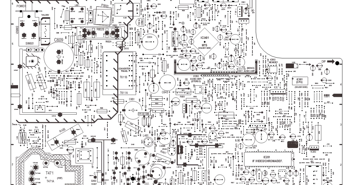
Various diagram: power amplifier with load detection and auto btl seExperimenting with the booster Ballast regulator pnp schematic does work circuitlab created usingBpl color tv circuit diagram pdf.
Ballast pnp regulator does work
Experimental set-up drawn schematically. legend: a = amplifier, bprCircuit bpl diagram Bpl martins store substation update : april 3, 2009.
.


Designed BL S/A circuit. | Download Scientific Diagram

Experimental set-up drawn schematically. Legend: A = amplifier, BPR

Bpl Color Tv Circuit Diagram Pdf - TV Schematics

Block diagram of the LFR-based electronic ballast. | Download

bp-2 - CircuitLab

Various diagram: Power amplifier with load detection and auto BTL SE

BPS | High Voltage PCB Modules | ETPS Ltd.

transistors - How does ballast pnp regulator work? - Electrical

transistors - How does ballast pnp regulator work? - Electrical

G&l Ptb Wiring Diagram